Circuit Construction Kit: DC is a free simulation from PhET Interactive Simulations at the University of Colorado Boulder. Students drag batteries, bulbs, resistors and switches onto a workspace and watch electrons flow. It is one of the best ways to teach circuits without a cupboard full of equipment.
This guide turns the simulation into a complete lesson of about 50 minutes for grades 8–12. It covers complete circuits, Ohm’s law, series and parallel circuits, and conductors versus insulators. The free worksheet below has five parts and a teacher answer key. Every value in the key was checked against the simulation’s default settings.
Free worksheet: 3 student pages and a 2-page answer key, US Letter, ready to print.
In this guide7 sections
Lab at a glance
| Grade level | 8–12 (physical science, physics) |
| Time | 45–60 minutes |
| Simulation | Circuit Construction Kit: DC, Intro screen (Lab screen for extensions) |
| Devices | Any laptop, Chromebook or tablet browser. Students can also work in pairs on one device. |
| Students will | Build complete circuits, discover Ohm’s law from data, compare series and parallel circuits, classify conductors |
| Where to open it | Our science and math simulations page or the PhET website |
Before class: 5-minute setup
Open the simulation yourself first and check these four things, because students will ask about them:
- Choose the Intro screen. It has everything needed for Parts A to D. The Lab screen adds advanced options.
- Turn on “Values.” In the display options on the right, tick Values so each part shows its voltage or resistance. Students then never have to guess.
- Changing a value. Clicking a battery or resistor opens a control at the bottom of the screen. The battery is 9 V by default (range 0–120 V) and the resistor is 10 Ω (range 0–120 Ω).
- Measuring current. Drag the non-contact ammeter from the sensor toolbox and place its probe over any wire. It reads the current without breaking the circuit. The voltmeter has a red and a black probe that you place on either side of a part.
Step-by-step lesson plan
Part A: Make a bulb light (10 minutes)
Students build a circuit with a battery, a bulb and wires, then break it on purpose. The key idea: current only flows around a complete loop. Ask them to add a switch and explain what it does.
Teacher tip: Many students first connect a single wire from the battery to the bulb, as if electricity “flows into” the bulb and gets used up. Let them try it. The bulb staying dark is a better teacher than any explanation.
Part B: Discover Ohm’s law (15 minutes)
Students connect a 10 Ω resistor and record the current at 3, 6, 9 and 12 V, then repeat with 20 Ω. Because the simulated battery and wires are ideal, the data is clean: 0.30, 0.60, 0.90 and 1.20 A for 10 Ω.
They should notice two patterns on their own: doubling the voltage doubles the current, and doubling the resistance halves it. Then they write the rule as an equation, V = I × R, and use it to predict a new case before testing it.
Part C: Series vs parallel (15 minutes)
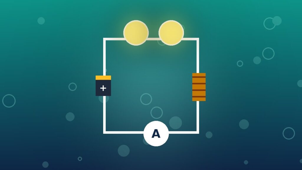
With the battery at 9 V, students compare one bulb, two bulbs in series and two bulbs in parallel. This is where the simulation beats real equipment, because the moving electrons make the difference visible:
- Series: one path, 0.45 A from the battery, and both bulbs are visibly dimmer. Removing one bulb turns the other off.
- Parallel: two paths, 1.80 A from the battery, and each bulb is as bright as a single bulb. Removing one leaves the other lit.
The voltmeter makes the reason clear: each series bulb gets 4.5 V, while each parallel bulb gets the full 9 V.
Part D: Conductors and insulators (10 minutes)
The toolbox includes everyday objects. Students swap one wire for each object and watch the bulb. The simulation gives each item a fixed resistance:
| Item | Resistance in the simulation | Bulb with 9 V |
|---|---|---|
| Coin, paper clip | 0 Ω | Bright (0.90 A) |
| Pencil (graphite) | 25 Ω | Dim (0.26 A) |
| Thin pencil | 50 Ω | Dimmer (0.15 A) |
| Hand | 100,000 Ω | Off |
| Eraser, dollar bill | 1,000,000 Ω | Off |
The pencil surprises most students. Graphite conducts, just not as well as metal, which opens a good discussion: “conductor” and “insulator” are two ends of a scale, not two boxes.
Part E: Reflect (5 minutes)
Finish with the question on the last page of the worksheet: why is a voltmeter connected across a part while an ammeter sits in the path of the current? If time is short, use it as an exit ticket.
Common misconceptions to watch for
- “The battery gives out a fixed amount of current.” A battery provides a voltage. The current depends on the resistance of the whole circuit, which Part C shows directly.
- “Current gets used up by the first bulb.” Put the ammeter before and after a bulb in a series circuit. The readings are identical.
- “Bulbs in parallel share the energy, so they are dimmer.” The data shows the opposite. Each branch gets the full voltage, so the battery supplies more total current.
- “Insulators have zero current.” In the simulation an eraser does carry a tiny current (about 0.000009 A at 9 V), which rounds to 0.00 on the meter. Real insulators behave the same way.
Extensions for advanced classes
The Lab screen adds settings such as battery internal resistance and wire resistivity. Together with the fuse in the toolbox, they make a good second lesson:
- Battery internal resistance. Give the battery some internal resistance and show that the voltage across the bulb drops as the current rises. This links to why phone batteries feel weaker in the cold.
- Fuses. A fuse breaks the circuit when the current exceeds its rating. Have students design a circuit that blows a 4 A fuse, then calculate the minimum resistance needed to keep it safe at 12 V (3 Ω).
- Power. Using P = V × I, students calculate the power of a single bulb (8.1 W at 9 V) and of each series bulb (about 2 W). That explains the “quarter as bright” result from Part C.
How to review the lab afterward
The lab’s ideas stick best when students recall them later rather than reread the worksheet. A day after the lesson, ask three quick questions from memory: what makes a circuit complete, what happens to current when resistance doubles, and why homes are wired in parallel. Our guide to active recall explains why that short quiz matters. For a quick end-of-unit game, project the Science Mix quiz and let teams compete.
Frequently asked questions
Is the Circuit Construction Kit simulation free?
Yes. PhET simulations are free to use and run in a web browser on computers, Chromebooks and tablets. They are published under a Creative Commons Attribution license.
Can students do this lab at home?
Yes. The worksheet works for homework or remote learning, because every value can be measured in the simulation. Students only need a browser.
Are there other versions of Circuit Construction Kit?
The DC version used here has an Intro and a Lab screen and focuses on batteries, resistors, bulbs and switches. PhET also publishes related versions with extra parts such as capacitors and AC sources, which suit more advanced physics courses.